 M17 Project Wiki
CC1200 M17
CC1200 supports M17. Both receive and transmit modes have been tested using CC1200EMK-420-470 evaluation board.
Note - apply a solder blob to pins 1 and 2 to pull up the RESET_N pin.
The key is reading/writing to the CFM_TX_DATA_IN / CFM_TX_DATA_OUT registers at a rate of 48kHz.
Steps to follow to get it working
- Give it a few milliseconds to power up, then send a reset command - 0x30 (1-byte write)
- Wait 100ms - probably the delay can be a lot less than that
- Use the config below to set up CC1200
- Send either 0x34 or 0x35 command (1-byte) to enable RX or TX mode
- If necessary (eg. using a simple XO instead of proper TCXO, caesium reference or hydrogen maser) - apply frequency compensation by writing int16_t value to register 0x2F0A. See the code at the end of this paragraph.
- Disable auto address increment for baseband SPI data tranfer - write 0 to register 0x2F06
- Start sending baseband samples in int8_t format to the
0x2F7Eregister - don’t pull SPI_CS line high after the first baseband byte, do it after all bytes are sent. First, send a 3-byte “start”:
tx_data[0]=0x2F|0x40;
tx_data[1]=0x7E;
tx_data[2]=*((uint8_t*)&baseband);
SPI_CS_down();
SPI_Send(tx_data, 3); //3-byte SPI transfer
//repeat the following lines:
while(something)
{
   tx_data[0]=*((uint8_t*)&baseband); //set accordingly
   SPI_Send(tx_data, 1); //1-byte transfer - continue until there are no baseband samples left
}
SPI_CS_up();
//TX done
The 0x40 sets burst write mode. Along with (6) we can actually keep reading/writing to the same register without the need of transferring address byte every time.
The receive mode works in the same way, but instead, the address of the register is 0x2F7D and we have to read it. The range is full int8_t. Just as for TX, don’t re-assert SPI_CS until the RX is complete.
tx_data[0]=0x2F|0xC0; //set burst read mode
tx_data[1]=0x7D;
tx_data[2]=0;
Samples for transmission have to be limited to -64..+64 range. Use the code below as a reference. The input is a 48kHz, mono, S16_LE .raw audio file, eg. generated with m17-cxx-demod tool.
#include <stdio.h>
#include <stdint.h>

FILE *fin, *fout;
int16_t r;
int8_t val;

int main(void)
{
	fin = fopen("M17_test_baseband.raw", "rb");
	fout = fopen("M17_output.txt", "wb");

	fprintf(fout, "int8_t baseband[24000]=\n{\n");

	for(uint16_t i=0; i<24000*2; i+=2)
	{
		fread(&r, 2, 1, fin);
		val=r/512.0;
		fprintf(fout, "\t0x%02X,\n", *(uint8_t*)&val);
	}

	fprintf(fout, "}");

	fclose(fin);
	fclose(fout);

	return 0;
}
Usually, there’s some frequency offset at the XO/TCXO. To compensate for that, use the following code:
int16_t offset=210;  //set accordingly
tx_data[0]=0x2F|0x40; //0x40 stands for burst mode
tx_data[1]=0x0A; //0x2F0A is where the freq offset register is
tx_data[2]=*((uint8_t*)&offset+1);
tx_data[3]=*((uint8_t*)&offset);

SPI_CS_down();
SPI_Send(tx_data, 4);
SPI_CS_up();
Sample M17 config for 435MHz TX/RX
const uint8_t cc1200_rx_settings[51*3] =
{
	0x00, 0x01, 0x08,
	0x00, 0x03, 0x09,
	0x00, 0x08, 0x1F,
	0x00, 0x0A, 0x9F, //deviation - about 3kHz full scale
	0x00, 0x0B, 0x00, //deviation
	0x00, 0x0C, 0x5D,
	0x00, 0x0D, 0x00,
	0x00, 0x0E, 0x8A,
	0x00, 0x0F, 0xCB,
	0x00, 0x10, 0xAC, //RX filter BW - 9.5kHz
	0x00, 0x11, 0x00,
	0x00, 0x12, 0x45,
	0x00, 0x13, 0x43, //symbol rate 2 - 1.5k sym/s
	0x00, 0x14, 0xA9, //symbol rate 1
	0x00, 0x15, 0x2A, //symbol rate 0
	0x00, 0x16, 0x37,
	0x00, 0x17, 0xEC,
	0x00, 0x19, 0x11,
	0x00, 0x1B, 0x51,
	0x00, 0x1C, 0x87,
	0x00, 0x1D, 0x00,
	0x00, 0x20, 0x14,
	0x00, 0x26, 0x03,
	0x00, 0x27, 0x00,
	0x00, 0x28, 0x20,
	0x00, 0x2B, 0x03, //output power - 0x03..0x3F (doesn't matter for RX)
	0x00, 0x2E, 0xFF,
	0x2F, 0x00, 0x1C,
	0x2F, 0x01, 0x02, //AFC, 0x22 - on, 0x02 - off
	0x2F, 0x04, 0x0C, //external oscillator's frequency is 40 MHz
	0x2F, 0x05, 0x09, //16x upsampler, CFM enable
	0x2F, 0x0C, 0x57, //frequency - round((float)435000000/5000000*(1<<16))=0x570000
	0x2F, 0x0D, 0x00, //frequency
	0x2F, 0x0E, 0x00, //frequency
	0x2F, 0x10, 0xEE,
	0x2F, 0x11, 0x10,
	0x2F, 0x12, 0x07,
	0x2F, 0x13, 0xAF,
	0x2F, 0x16, 0x40,
	0x2F, 0x17, 0x0E,
	0x2F, 0x19, 0x03,
	0x2F, 0x1B, 0x33,
	0x2F, 0x1D, 0x17,
	0x2F, 0x1F, 0x00,
	0x2F, 0x20, 0x6E,
	0x2F, 0x21, 0x1C,
	0x2F, 0x22, 0xAC,
	0x2F, 0x27, 0xB5,
	0x2F, 0x32, 0x0E,
	0x2F, 0x36, 0x03,
	0x2F, 0x91, 0x08
};

const uint8_t cc1200_tx_settings[51*3] =
{
	0x00, 0x01, 0x08,
	0x00, 0x03, 0x09,
	0x00, 0x08, 0x1F,
	0x00, 0x0A, 0x06, //deviation - 5kHz full scale
	0x00, 0x0B, 0x01, //deviation
	0x00, 0x0C, 0x5D,
	0x00, 0x0D, 0x00,
	0x00, 0x0E, 0x8A,
	0x00, 0x0F, 0xCB,
	0x00, 0x10, 0xAC, //RX filter BW - 9.5kHz (doesn't matter for TX)
	0x00, 0x11, 0x00,
	0x00, 0x12, 0x45,
	0x00, 0x13, 0x43, //symbol rate 2 - 1.5k sym/s
	0x00, 0x14, 0xA9, //symbol rate 1
	0x00, 0x15, 0x2A, //symbol rate 0
	0x00, 0x16, 0x37,
	0x00, 0x17, 0xEC,
	0x00, 0x19, 0x11,
	0x00, 0x1B, 0x51,
	0x00, 0x1C, 0x87,
	0x00, 0x1D, 0x00,
	0x00, 0x20, 0x14,
	0x00, 0x26, 0x03,
	0x00, 0x27, 0x00,
	0x00, 0x28, 0x20,
	0x00, 0x2B, 0x03, //output power - 0x03..0x3F
	0x00, 0x2E, 0xFF,
	0x2F, 0x00, 0x1C,
	0x2F, 0x01, 0x22,
	0x2F, 0x04, 0x0C, //external oscillator's frequency is 40 MHz
	0x2F, 0x05, 0x09, //16x upsampler, CFM enable
	0x2F, 0x0C, 0x57, //frequency - round((float)435000000/5000000*(1<<16))=0x570000
	0x2F, 0x0D, 0x00, //frequency
	0x2F, 0x0E, 0x00, //frequency
	0x2F, 0x10, 0xEE,
	0x2F, 0x11, 0x10,
	0x2F, 0x12, 0x07,
	0x2F, 0x13, 0xAF,
	0x2F, 0x16, 0x40,
	0x2F, 0x17, 0x0E,
	0x2F, 0x19, 0x03,
	0x2F, 0x1B, 0x33,
	0x2F, 0x1D, 0x17,
	0x2F, 0x1F, 0x00,
	0x2F, 0x20, 0x6E,
	0x2F, 0x21, 0x1C,
	0x2F, 0x22, 0xAC,
	0x2F, 0x27, 0xB5,
	0x2F, 0x32, 0x0E,
	0x2F, 0x36, 0x03,
	0x2F, 0x91, 0x08
};
For TX mode, deviation control registers (DEVIATION_M and MODCFG_DEV_E) are set for about 5kHz. For RX they are set to about 3kHz. Symbol rate is set to 24k for TX and 1.2k for RX. Nobody knows why these settings work :) RX BW is about 9.5kHz. CFM is enabled in both modes. AFC can be enabled in RX mode by writing to register 0x2F01.
Results
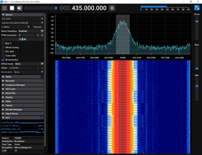
CC1200 transmission at 435 MHz decoded with SDR++:
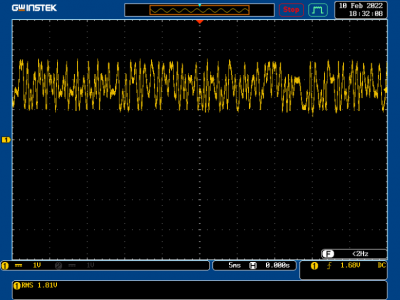
M17 RF signal received by CC1200 (CFM_RX_DATA_OUT register output fed to DAC):

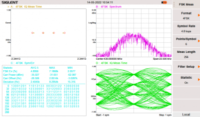
M17 signal transmitted by CC1200: