 M17 Project Wiki
Using Module17 with Icom IC-F506X/606X or IC-F306X/406X radios
Introduction
This series of ICOM radios are extremely interesting due to their internal header that allows to “patch” into the Tx and Rx patch, giving access to unfiltered audio to and from baseband, plus microphone inputs and speaker outputs. However, if you so require, you can also connect a Module17 modem board using the external DB-25 connector - both are documented here.
External version - mobile radios only
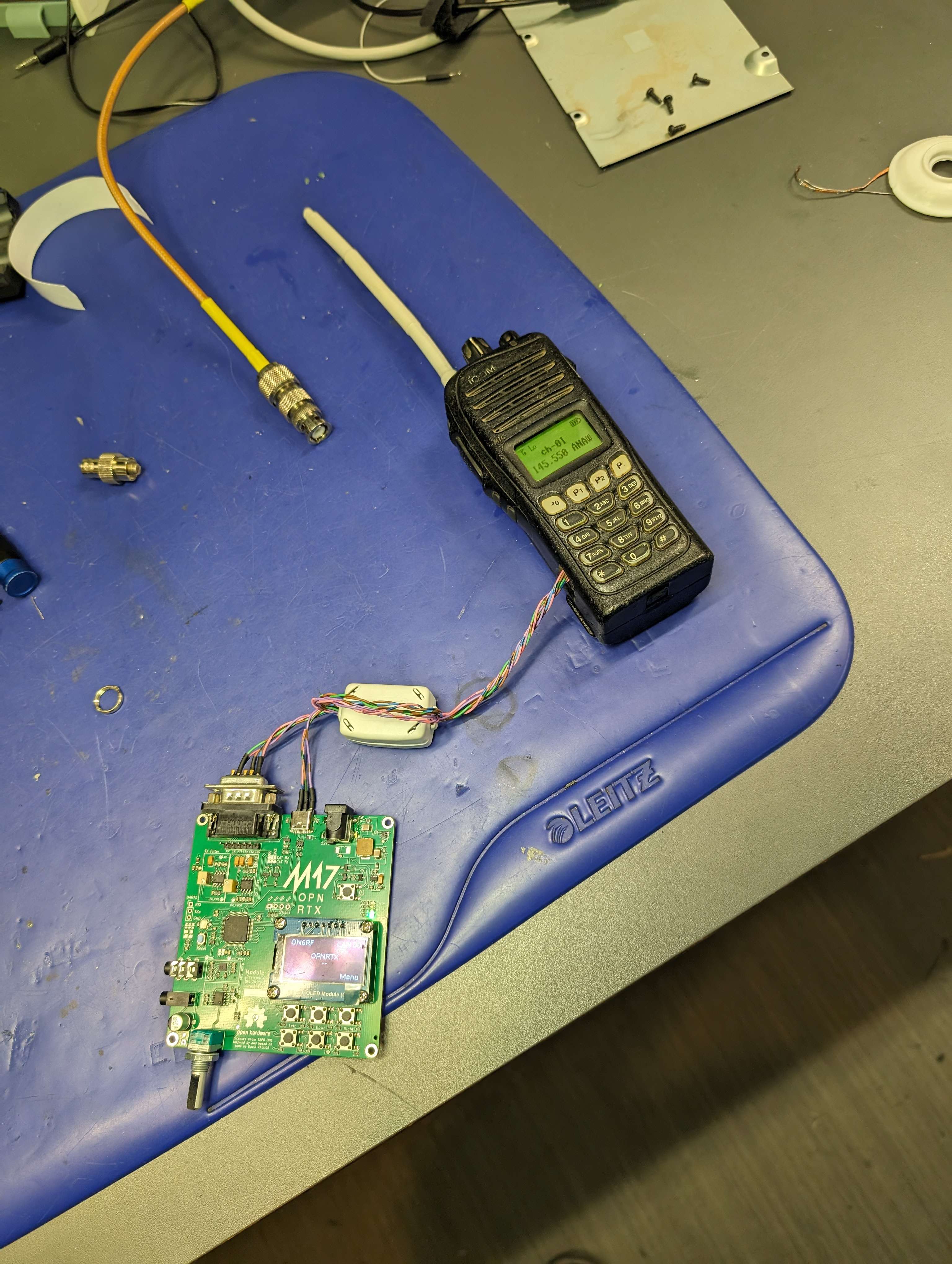
Module17 can be hooked to the DB-25 connector at the back of the radio.
| Module17 Pins | ICOM Radio external connector |
|---|---|
| GND (DB9 - pin 8) | GND (DB25 - pin 14) |
| RX (DB9 - pin 6) | DISC (DB25- pin 9) |
| TX (DB9 - pin 2) | EXMOD (DB25 - pin 8) |
| PTT_OUT (DB9 - pin 5) | EPTTO (DB25 - pin 4) |
| +12V (DB9 - pin 9) | VCC (DB25 - pin 11 - optional) |
You’ll also need to modify some jumpers to bypass all filters coming from the discriminator/modulator, namely:
- Cut “K”
- Bridge “L”
- Bridge “D”
Internal version - mobile and portable radios
Getting that mod working with Module17 requires both hardware and software mods.
Modifying Module17’s firmware
Those radios use the PTT “Active High”, which is not natively compatible with Module17. You’ll need to add pull-ups (more on that in the next section) and invert the logic of PTT. As of writing this document, there isn’t an option (yet) to invert it. You’ll need to do it on the Fw source file. If only using basic connections, while keeping the external mic/speaker connected to Module17, you just need to modify the PTT out logic, in platform/drivers/baseband/radio_Mod17.cpp:
void radio_enableRx()
{
    radioStatus = RX;
    gpio_clearPin(PTT_OUT);

...

void radio_enableTx()
{
    radioStatus = TX;
    gpio_setPin(PTT_OUT)
Replace with
void radio_enableRx()
{
    radioStatus = RX;
    gpio_setPin(PTT_OUT);

...

void radio_enableTx()
{
    radioStatus = TX;
    gpio_clearPin(PTT_OUT)
If you wish to pipe the audio from/to Module17 back into the radio and use the internal mic/speakers, you’ll also need to invert the PTT_in logic, in platform/targets/Module17/platform.c
bool platform_getPttStatus()
{
    /* PTT line has a pullup resistor with PTT switch closing to ground */
    return (gpio_readPin(PTT_SW) == 0) ? true : false;
}
Replace with
bool platform_getPttStatus()
{
    /* PTT line has a pullup resistor with PTT switch closing to ground */
    return (gpio_readPin(PTT_SW) == 1) ? true : false;
}
Basic connections while using the external mic/speaker
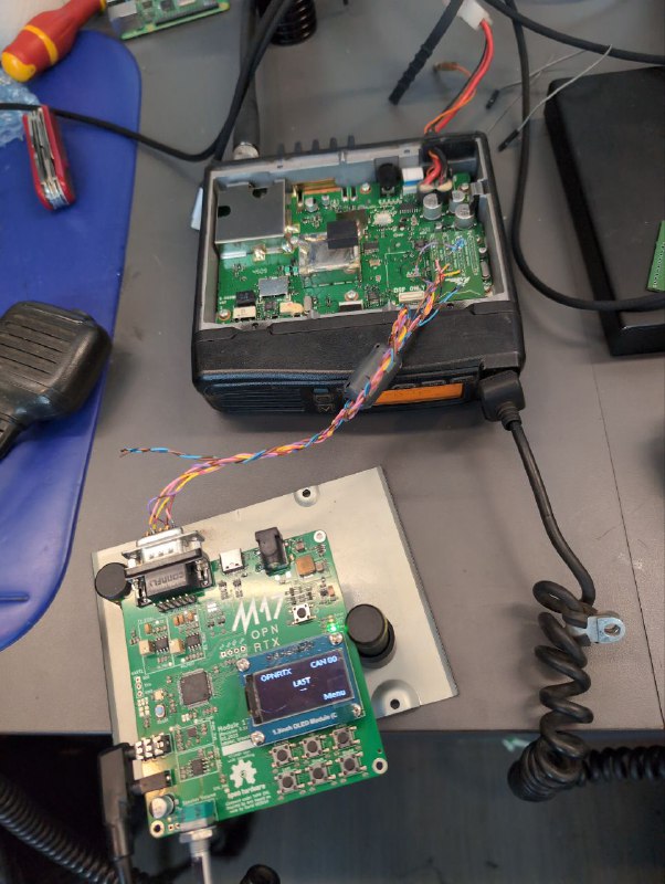
You’ll need to access the 40-pin expansion header inside the radio. Either solder directly to it, or get Freddruppel’s breakout board.
Ideally, J2-DSP should be used as this is where the usual UT-126 dPMR/NXDN digital module resides. However, as we also need PTT in/out, J1 is the only suitable candidate.
 If you only need to get baseband in/out access (as you would with any other radio), here are the connections:
| Module17 Pins | 40-pin connector |
|---|---|
| GND (DB9 - pin 8) | Pin 2, 17 or 39 - GND |
| +12V (DB9 - pin 9) | Pin 37 - VCC |
| RX (DB9 - pin 6) | Pin 31 - DISC |
| TX (DB9 - pin 2) | Pin 13 - SIGO |
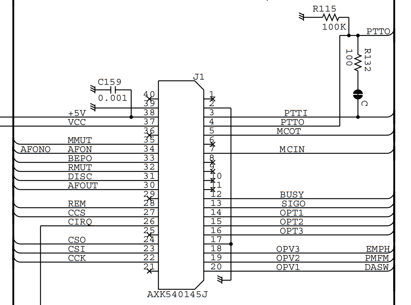
| PTT_OUT (DB9 - pin 5) | Pin 4 - PTTO (Add a 1K pullup to 5V - pin 38!) |
You’ll also need to modify some jumpers to bypass all filters coming from the discriminator, namely:
- On mobile radios: cut “K” and bridge “L”
- On handsets radios: cut “CP2” and bridge “CP3”
Don’t forget the Pull-up! Otherwise the radio won’t be able to key up.
On Module17, invert phase on TX only. On the radio, program a classic Analog - wide channel. Level adjustment on Tx is quite simple: have an SDR on the side with SDR++, monitor the deviation until it falls within the guides. You’ll need to push it quite high! For Rx, an oscilloscope helps a lot, set the levels at around 2V p-p when coming out of the RX Baseband filter. Keep wire length to a minimum, adding a ferrite might also help (or just use shielded wire) to keep RFI at bay.
Patch into the radio’s internal speaker/mic/speaker
This requires splitting the Tx/Rx path completely to put Module17 “in the middle”. Additional jumpers on the radio’s PCB must be cut:
- On mobile radios: A, B and C.
- On handsets: MIC, AFOUT, PTT.
Don’t forget to first modify the PTT input logic in firmware.
Module17 doesn’t initially break out Mic in, audio out or PTT in as they’re supposed to come out the Kenwood connector. You’ll need to go get the signals yourself… We found the easiest way was to solder a few wires underneath:
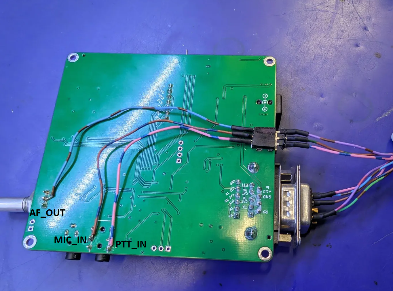
- AF_IN can be soldered on the potentiometer’s middle pin
- MIN_IN on the large jack’s middle pin
- PTT_IN on the large jack’s furthemost (closest to the PCB’s edge) pin
Furthermore, you’ll need to add a resistive divider on the PTT_IN line coming from the radio, as it’s 5V, which the STM32 on the Module17 might not appreciate. Here’s the complete wiring, including what was mentioned in the previous section:
| Module17 Pins | 40-pin connector |
|---|---|
| GND (DB9 - pin 8) | Pin 2, 17 or 39 - GND |
| +12V (DB9 - pin 9) | Pin 37 - VCC |
| RX (DB9 - pin 6) | Pin 31 - DISC |
| TX (DB9 - pin 2) | Pin 13 - SIGO |
| PTT_OUT (DB9 - pin 5) | Pin 4 - PTTO (Add a 1K pullup to 5V - pin 38!) |
| AF_OUT (pot middle pin) | Pin 30 - AFOUT |
| MIC_IN (jack’s middle pin) | Pin 7 - MCIN |
| PTT_IN (jack’s last pin) | Pin 3 - PTTIN (Through a resistive divider: two 2.7k resistors in series between pins 2 and 3, wire to Module17 in the middle) |